




News & Blogs
Executive Summary: Laser marking and coding on curved, sloped, or stepped industrial components often fails due to dynamic focal depth limitations. When a surface gradient exceeds the laser beam’s depth of focus (Rayleigh range), energy density drops exponentially, resulting in uneven contrast, distorted 2D codes, and high verification failure rates (ISO/IEC 15415/15416). This engineering guide breaks down the optics of focal depth failure, parameter adjustments to extend focal range, 3D dynamic focus hardware integration, and practical troubleshooting protocols for marking complex geometries.
???? Why Fixed 2D Lasers Fail on Curved and Uneven Substrates
Standard 2D laser marking systems utilize a fixed F-theta field lens to focus the laser beam onto a single flat X-Y focal plane. When the part geometry extends above or below this plane—such as on extruded pipes, automotive shafts, curved medical tools, or stepped recessed housings—the beam deflocculates.
Two distinct physical degradation modes occur once the target surface moves outside the laser’s Depth of Focus (DOF):
Power Density Decay: As the beam goes out of focus, the spot diameter (w_0) expands. Peak power density (I_0) decreases inversely with the square of the spot radius:
I0 = Ppeak / (π × w02)
???? Note: For pulsed lasers (Fiber, UV, MOPA), engineers must use peak power (Ppeak = Pavg / (f × τ), where f is frequency and τ is pulse duration) rather than average power (Pavg) to accurately calculate peak irradiance at the focal spot. A 2× increase in spot size reduces peak power density by 75%, causing marks to fade from dark gray to invisible.
Geometric Spot Distortion: On steep angles, a circular laser spot strikes the surface as an elongated ellipse. This stretches individual cells in DataMatrix or QR codes, causing Axial Non-Uniformity and Grid Distortion failures during visual inspection.
1. Calculating Depth of Focus (Rayleigh Range)
To determine whether your application requires optical tuning or a full 3D dynamic focus system, calculate your laser's theoretical Rayleigh Range (zR):
zR = (π × w02) / λ
Where:
w0= Focused spot radius at beam waist
λ= Laser wavelength (e.g., 1064nm Fiber, 355nm UV)
The total acceptable Depth of Focus (DOF) is approximately 2×z_R.
Practical Industry Tolerances
Standard 2D Fiber Laser ( F=160nm lens): Total engineering DOF is roughly ±1.5mm to ±2.0mm (depending on acceptable spot size growth and marking contrast requirements).
Long Focal Length Lens ( F=254mm lens): Total DOF increases to ±3.5mm to ±5.0mm, but at the expense of a larger spot size and lower energy concentration.
If your component's surface curvature or height differential exceeds these tolerances, standard 2D marking will produce illegible, out-of-focus borders.
2. Three Engineering Solutions for Marking Complex Geometries
Solution 1: Optical & Parameter Tuning (For Height Changes <4mm)
For subtle curves or shallow steps, you can extend the workable focal range without replacing hardware:
Swap to a Longer F-Theta Lens: Increasing focal length (e.g., from F=160nm to F=254mm) flattens the Rayleigh range curve, expanding the usable DOF up to ≈ ±4mm. Trade-off: Requires higher laser power output to compensate for lower spot energy density.
Increase Pulse Frequency & Overlap: Raise repetition rates (e.g., >60kHz on MOPA Fiber) and decrease line hatch spacing (0.02mm -0.03mm). This compensates for out-of-focus power drop-off by increasing thermal energy deposition per unit area.
Optimize Beam Expander Ratio: Adjust the beam expander to narrow the input beam diameter entering the galvo scanner, which mechanically widens the waist of the focused spot, increasing depth of field.
Solution 2: Hardware Upgrade to 3D Dynamic Focus Systems (For Height Changes >4mm)
When surface depth variations exceed 5mm-50mm+, dynamic Z-axis compensation is mandatory.
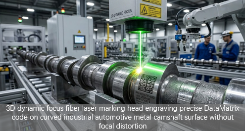
Dynamic Focus Module (3D Galvo): A dynamic focus system places a high-speed linear voice-coil or piezo-driven optic before the X - Y galvo scanners.
Real-Time Z-Adjustment: As the galvo mirrors sweep across a curve, the Z - axis lens shifts positions in microseconds, continuously shifting the focal point to match the 3D surface profile.
CAD Surface Mapping: 3D marking software imports the part's STEP or STL file, automatically projecting 2D DataMatrix codes, text, or logos onto cylinders, cones, spheres, or freeform surfaces without optical distortion.
???? Vision-Guided 3D Marking (For Random Part Positioning)
In automated production lines where parts arrive at the marking station with inconsistent orientation or height (e.g., forged automotive components in trays), static CAD mapping is insufficient. A structured-light 3D scanner or laser profilometer mounted upstream captures the exact X,Y,Z coordinates of each part in real time. This spatial data is fed to the 3D dynamic focus controller on-the-fly, enabling "mark anywhere, regardless of height" capability without expensive mechanical clamping or indexing.
Solution 3: Non-Laser Alternatives for Ultra-Deep Recesses (CIJ / High-Throw TIJ)
When laser line-of-sight is obstructed by steep walls or deep cavities:
Continuous Inkjet (CIJ): Maintains code legibility at throw distances up to 15mm-20mm from the substrate, making it resilient against extreme surface contours.
Extended Throw Distance TIJ: High-pressure solvent TIJ cartridges with optimized nozzle architecture provide clear marks on curved packaging at throw distances up to 6mm-8mm.
3. Technology Selection Matrix: Fixed 2D vs. 3D Dynamic Focus vs. Extended-Throw Inkjet
Technical Parameter | Fixed 2D Laser (F=160mm) | Extended 2D Laser (F=254mm) | 3D Dynamic Focus Laser | High-Throw CIJ / TIJ |
Max Surface Height Differential | ≤2.0mm | ≤4.0mm | Up to 50mm-100mm+ | ≤15.0mm |
Spot Size Uniformity | Degrades off-center | Moderate | 100% Constant Across Surface | N/A (Droplet size fixed) |
Max Surface Inclination Angle | ≤15° | ≤25° | Up to 60°-75° | ≤45° |
Marking Speed | High | High | High (Microsecond -tracking) | Very High |
System Complexity & CapEx | Low (Baseline 2D) | Low (Lens cost only) | Higher upfront investment | Moderate CapEx / Ongoing ink |
Best Substrate Application | Flat plates, shallow curves | Smooth cylinders, slight steps | Tubes, automotive valves, complex 3D parts | Concave bottle bottoms, deep channels |
4. Step-by-Step Optimization Checklist for Engineers
If you are experiencing out-of-focus code fading or distortion on an active production line, follow this diagnostic sequence:
Measure Total Height Variation (ΔZ): Use a dial indicator or laser displacement sensor to measure the peak-to-valley height across the marking zone.
Center the Focal Plane at Mid-Height: Do not set the focal point at the highest or lowest point of the component. Set the laser focus at the exact midpoint of ΔZ to split the focal error evenly between +ΔZ/2 and -ΔZ/2.
Switch 2D Matrix to 1:1 Aspect Ratio Corrections: In software, apply anamorphic scaling (adjusting X/Y scaling ratios separately) to pre-compensate for geometric stretching on angled slopes.
Calibrate 3D Mesh Offset (3D Systems Only): Ensure the focal displacement table matches the actual physical lens calibration. Perform a 9-point grid verification on a 3D calibration block to verify focal depth tracking across the entire field.
5. Frequently Asked Questions (FAQ)
Q1: Can software correction fix out-of-focus laser marking without changing hardware?
A: Software can correct geometric distortion (stretching) by altering the input shape of the graphic. However, software alone cannot fix energy density decay caused by a deflocculated laser spot. If the peak power density drops below the thermal threshold of the material, you must adjust physical optics, increase power, or upgrade to a 3D dynamic focus system.
Q2: How does a 3D dynamic focus laser machine know the curvature of the part?
A: The operator imports a 3D CAD model (STEP/STL file) into the laser control software and aligns the mark onto the digital geometry. For lines with high part-to-part height variance, an inline 3D laser displacement sensor or vision system measures the part geometry on-the-fly and feeds Z-axis offset data directly to the galvo scanner before firing.
Q3: What is the maximum slope angle a 3D laser marking machine can handle?
A: Most 3D dynamic focus systems can mark effectively on surface angles up to 60°-75° relative to the beam axis. Beyond 75°, beam reflections (fresnel reflection losses) increase significantly, requiring rotary axis integration (4th axis indexer) to rotate the part during marking.
Q4: Is a 3D dynamic focus laser system worth the higher upfront cost?
A: For flat or gently curved parts (<2mm height variation), a standard 2D laser with a long-focal-length lens (F=254mm) is usually the most cost-effective solution. For complex geometries with >4mm height differential—especially on automotive castings, forged shafts, or medical implants—a 3D dynamic focus system delivers ROI within 12–18 months by eliminating scrap from unreadable codes, removing secondary indexing operations, and streamlining SKU changes.
???? Explore Our Technical Traceability Matrix
Anodized Aluminum Components: How to Print High-Contrast Barcodes on Anodized Aluminum Components
HDPE vs. PET Bottles: Why Laser Marking Setup Changes for Each Substrate (CO2 vs. UV)
Cold Beverage Lines: Solving Code Smudging on Cold Beverage Lines: Condensation-Resistant Coding Guide
Medical Metals: FDA UDI Compliance on Surgical Tools: How to Stop Rust & Fading After Passivation