




News & Blogs
Executive Summary: Laser marking thin plastic films (PE, PP, PET, PVC, medical tubing, and flexible packaging) frequently results in severe quality defects: localized charring, sub-surface bubbling, structural warping, or complete melt-through. These thermal damage modes distort 2D DataMatrix and QR codes, causing failed ISO/IEC 15415/15416 verification scans and high scrap rates. This engineering guide breaks down the absorbency photothermal optics behind Heat-Affected Zone (HAZ) expansion, provides immediate parameter tuning steps to control energy dwell time, and compares 355nm UV "cold laser" processing against MOPA short-pulse technology for thin substrate integrity.
???? Quick Selection Guide (For Procurement & Process Engineers)
If you are marking... | Start with... | Why? |
Transparent films (PET, PE, PP) | 355nm UV Laser | Zero thermal damage, photochemical surface-only mark |
Opaque engineering plastics (ABS, PC, Nylon) | MOPA Fiber (2–10ns pulse) | Cost-effective, eliminates burning, high dark contrast |
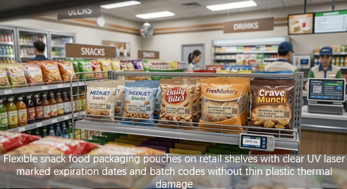
Flexible packaging pouches | 355nm UV Laser | Zero pinholes, preserves barrier & seal integrity |
Thick-walled plastic parts (>2mm) | MOPA or Standard Fiber | Larger thermal mass dissipates heat naturally |
???? The Physics of Thermal Damage on Heat-Sensitive Plastics
Plastics possess low thermal conductivity and low melting thresholds. When irradiated by conventional infrared lasers (such as 1064nm Continuous-Wave or standard Fiber lasers), thermal energy cannot dissipate quickly enough into the surrounding material.
Three distinct thermal failure modes occur when energy input exceeds the thermal tolerance of thin plastics (<1.0 mm thickness):
Charring & Discoloration (Burning): Excessive heat breaks down the polymer chains and organic pigments, causing carbonization. Instead of a sharp, crisp mark, the plastic turns yellow, brown, or burnt black.
Sub-surface Gas Trapping (Bubbling): Intense localized heating causes internal additives, moisture, or low-molecular-weight polymers to vaporize rapidly before reaching the surface. The trapped gas forms microscopic bubbles, disrupting code legibility.
Structural Warping & Pinhole Punctures (Melt-Through): When the Heat-Affected Zone (HAZ) extends beyond the target marking depth, localized thermal expansion causes the thin film to shrink, curl, or burn through completely.
Absorbed Energy Density & Heat Accumulation Equation
The actual absorbed energy density (Eabsorbed) deposited into the plastic matrix per unit area is governed by the material's spectral absorption, pulse frequency, and pulse overlap:
Eabsorbed = α(λ) × (Pavg / (f × A)) × (1 / (1 - Op))
Where:
α(λ) = Material absorption coefficient at the specific laser wavelength λ (value between 0 and 1)
Pavg = Average laser power (W)
f = Pulse repetition rate / frequency (kHz)
A = Focal spot area (π × w02)
Op = Pulse overlap ratio along the scan line
To prevent thermal degradation, engineers must maximize peak power while minimizing average thermal accumulation by selecting a wavelength where α(λ) is optimized for photochemical reaction rather than thermal heating.
1. Five Immediate Parameter Tweaks (No Hardware Upgrade Required)
If your existing laser marking system is burning or melting thin plastic components, apply these parameter adjustments in your control software before purchasing new equipment:
Increase Frequency (f) and Scan Speed (v): Raising the pulse repetition rate while increasing the galvo scan speed reduces individual pulse energy and prevents localized heat accumulation.
Reduce Line Hatching Density: Decrease the hatch spacing (e.g., expand from 0.02 mm to 0.05 mm - 0.08 mm). Overlapping hatch lines are the leading cause of melt-through on thin films.
Enable Wobble / Outline Mode: Instead of using a dense raster fill, apply a vector outline or a high-frequency wobble stroke (oscillating beam) to reduce dwell time per unit area. This limits heat accumulation by distributing the laser's total exposure over a slightly wider scan path.
Optimize Jump and Delay Timings: Eliminate "end-point burning" (where the laser pauses at vector corners or line ends) by fine-tuning the Laser-On Delay, Laser-Off Delay, and End Delay parameters.
Implement Compressed Air Assist: Direct a cross-jet of dry compressed air at the focal point to actively cool the substrate surface and clear out thermal vapor.
2. Hardware Solutions: Wavelengths & Pulse Control
When parameter tuning reaches its physical limits, selecting the correct laser source architecture is mandatory for heat-sensitive plastics.
Option A: UV Lasers (355nm - "Cold Processing" / Photochemical Breakdown)
Unlike infrared lasers that rely on photothermal heating (melting/burning), 355nm UV lasers utilize photochemical processing.
Mechanism: UV photons carry ultra-high photon energy (3.49 eV) capable of directly breaking the C-C and C-H molecular bonds of polymers without generating significant heat.
HAZ Elimination: Heat-Affected Zone (HAZ) is reduced to near-zero.
Result: Perfectly crisp, high-contrast marks on ultra-thin PET films, PE pouches, and medical-grade IV tubing without any surface swelling, discoloration, or pinhole punctures.
Option B: MOPA Fiber Lasers (Adjustable Pulse Width: 2ns – 500ns)
Standard Q-switched fiber lasers have a fixed pulse width (typically 100ns – 120ns), which delivers thermal energy for too long on plastic surfaces.
Mechanism: Master Oscillator Power Amplifier (MOPA) fiber lasers allow operators to shorten the pulse duration down to 2ns – 10ns.
Result: Extremely short pulses vaporize or color-change the surface additives before thermal heat has time to conduct deeper into the plastic substrate, eliminating warping on opaque engineering plastics (ABS, PC, Nylon).
3. Technology Selection Matrix: Material vs. Wavelength & Damage Risk
Plastic Substrate | Standard Fiber Laser (1064nm) | MOPA Fiber Laser (Short Pulse) | CO2 Laser (10.6μm / 9.3μm) | UV Laser (355nm "Cold Processing") |
Thin PET Film (<0.2mm) | ???? High Melt/Puncture Risk | ???? Moderate (Requires tuning) | ???? Good (9.3μm absorbs better) | ???? Best (Zero damage / Perfect contrast) |
White/Transparent PE/PP | ???? Severe Burning/Yellowing | ???? Limited Contrast | ???? Engraved/Melts | ???? Best (High contrast photo-chemical mark) |
Medical PVC / Silicone Tubing | ???? Toxic Charring/Bubbling | ???? Moderate | ???? High Melt Risk | ???? Best (UDI compliant / Smooth surface) |
Opaque ABS / PC Housings | ???? Foaming / High Heat | ???? Excellent (Dark mark / No burn) | ???? Rough Engraving | ???? Excellent (Ultra-fine mark) |
Flexible Packaging Film | ???? Melt-Through | ???? Melt-Through | ???? Pinholes possible | ???? Best (Surface-only mark) |
4. Step-by-Step Optimization Protocol for Production Line Engineers
Follow this systematic procedure to eliminate thermal damage during pre-production setup:
Verify Material Absorption Curve α(λ): Ensure the plastic substrate contains suitable absorption additives if attempting infrared marking, or switch directly to 355nm UV for raw polymers.
Determine the Thermal Damage Threshold: Start at 10% average power and increase in 5% increments until the mark is legible. Note the exact power setting where bubbling, charring, or melt-through begins.
Set Power to 80% of Damage Threshold: Lock the operating power below this boundary and adjust mark speed (v) upwards to maintain production line throughput.
Inspect Under Magnification: Use an optical microscope or 2D barcode verifier to inspect for micro-cracks, pinhole burns, or axial non-uniformity caused by thermal expansion.
5. Frequently Asked Questions (FAQ)
Q1: Why does white plastic turn yellow or brown during laser marking?
A: Yellowing or browning is a symptom of thermal carbonization. The laser's pulse width is too long or the energy density is too high, causing the polymer chains and flame-retardant additives to decompose thermally rather than changing color cleanly.
Q2: Can a UV laser mark thin plastic film without causing pinhole leaks?
A: Yes. Because 355nm UV lasers operate via photochemical bond-breaking rather than thermal melting, the marking effect is strictly confined to a surface depth of a few micrometers, preserving the barrier properties and seal integrity of thin flexible packaging.
Q3: Is MOPA fiber laser technology sufficient to replace UV laser marking for all plastics?
A: MOPA lasers are excellent and cost-effective for dark or opaque engineering plastics (like ABS, Polycarbonate, and Nylon) because ultra-short pulse widths (2ns - 10ns) restrict heat conduction. However, for transparent films, white PE/PP, HDPE, and sensitive medical tubing, a 355nm UV laser remains the superior solution.
HDPE vs. PET Substrate Setup:
Packaging Code Adhesion & Rub-Off:
Flexible Film QR Scannability:
Glass Bottle UV Laser Marking: