




News & Blogs
Estimated reading time: 5 minutes
Direct Part Marking (DPM) on metal components is essential for full-lifecycle traceability in automotive, aerospace, and heavy industrial manufacturing. However, etching readable 2D barcodes directly onto raw steel, aluminum, or machined parts poses significant challenges on the shop floor.
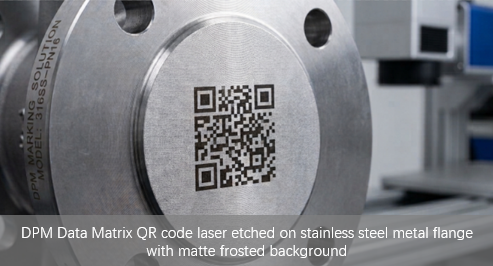
Operators frequently encounter three primary issues: optical glare blinding industrial AOI scanners, codes losing contrast after post-process chemical washes, and surface roughness distorting tiny matrix elements.
Here is a practical troubleshooting guide to help you achieve Grade A scannability under ISO/IEC TR 29158 (AIM DPM) standards on metal substrates.
Note: While the industry broadly uses the term "QR code" for 2D barcodes, Data Matrix (ECC 200) is often preferred in DPM applications due to its smaller footprint and superior error correction on tiny metal surfaces.
1. Solved: The Top 3 Metal DPM Marking Headaches
Problem 1: Mirror Glare from Machined Metals (Scanner Blindness)
Polished stainless steel and raw aluminum reflect scanner LED lighting like a mirror, blinding optical decoding engines.
Fix: Program your fiber laser to apply a micro-hatched, matte-frosted base layer before etching the dark code modules. This non-reflective base eliminates glare and dramatically improves Cell Contrast (Rmax - Rmin).
Problem 2: Contrast Loss After Degreasing & Oil Baths
Harsh degreasers, rust-proofing oils, or heat treatments don't wash laser marks away, but oil residues can settle into shallow micro-pits, destroying dark-to-light contrast.
Fix: Use deep laser engraving (≥ 50μm) or subsurface laser annealing (producing black oxide marks) to ensure contrast remains intact even after heavy chemical exposure. For stainless steel, MOPA-configuration fiber lasers are ideal for achieving precise black annealing marks.
Problem 3: Rough Surface Textures Distort Code Modules
Cast iron and rough forgings have uneven surface pits that disrupt delicate 2D matrix grids.
Fix: Increase the module size (X-dimension) to at least 0.35 mm. A larger module prevents surface roughness from breaking individual code elements.
2. Choosing the Right Marking Technology for Metal Substrates
Option A: Fiber Laser Marking Machine
Marking Permanence: 100% Permanent (Highly resistant to heat & acids)
Maintenance & Consumables: Minimal consumables (protective lenses)
Primary Factory Advantage: Etches directly into metal structure; ultra-high precision (≤ 10μm) for high-density DPM codes.
Option B: Continuous Inkjet Printer (CIJ)
Marking Permanence: Non-permanent (Vulnerable to solvents & abrasion)
Maintenance & Consumables: High maintenance (requires ink & solvents)
Primary Factory Advantage: Non-contact, high-speed marking for temporary batch numbers on moving cans.
Option C: TIJ High-Res Inkjet Printer
Marking Permanence: Non-permanent (Fast-drying solvent ink)
Maintenance & Consumables: Low maintenance (cartridge-based)
Primary Factory Advantage: Clean, portable operation for offline metal tags and warehouse storage labels.
Important Note: For permanent DPM traceability compliance (e.g., automotive PPAP or aerospace standards), only laser marking qualifies as true direct part marking. Ink-based CIJ and TIJ systems do not meet DPM permanence requirements and are suitable for temporary lot coding only.
Form Factor Tip: While stationary inline lasers excel on automated conveyor lines, heavy or immobile workpieces (such as structural steel beams, large valves, or castings) require a portable laser marker to bring the beam directly to the component.
3. Quick Checklist for 100% Scannable Metal Codes
Optimize Focal Distance: Even a 1 mm shift in focal length can broaden the laser spot size, degrading module edge sharpness and lowering axial uniformity.
Verify Lighting Angle: Set industrial scanners at a 30° to 45° illumination angle rather than direct 90° perpendicular mounting to prevent direct bounce reflection.
Maintain Clean Optics Daily: Metal dust and oil vapors accumulate quickly on laser protective lenses, reducing pulse energy and causing weak, uneven marks.
Validate with a DPM Verifier: Use a dedicated ISO-compliant DPM verifier to confirm Grade A or B ratings during setup, rather than relying solely on standard handheld barcode readers.
Conclusion
Achieving reliable DPM 2D codes on metal requires matching the laser process to the substrate's optical characteristics. Selecting the proper laser configuration guarantees seamless barcode decoding across the entire product lifecycle.
Explore Our Complete Material Traceability Matrix
Need QR code scannability solutions for other industrial substrates? Read our engineering guides:
???? Flexible Films & Plastic Packaging: How to Improve QR Code Scannability on Flexible Films and Plastic Packaging
???? PCB Circuit Boards: How to Print Micro QR Codes on PCB Boards
???? Glass & Glossy Packaging: How to Eliminate Refraction Glare for QR Code Marking on Glass & Glossy Containers